A speed controller is one of the key components used to control cylinder movement. Although small in size, it directly affects whether a cylinder operates smoothly, vibrates, or moves too aggressively.
But do you know how to properly use a speed controller?
This guide explains installation, selection, adjustment steps, and key precautions. If you are unsure how to choose a speed controller, this article will help you better understand the essentials.
Table of Contents
What Is a Speed Controller?
A speed controller is a pneumatic component used to adjust cylinder speed. By controlling the flow rate of compressed air, it regulates the forward and return speed of a cylinder.
It operates on the principle of one-way flow control, allowing speed adjustment in one direction while permitting free exhaust in the opposite direction. This ensures that cylinder motion does not become too fast or unstable, maintaining smooth and steady operation.
Speed controllers are commonly installed at:
- Cylinder ports
- Pneumatic grippers
- Small fixtures
- Motion points requiring precise speed control
Their purpose is to ensure cylinder movement is not too fast, does not stick, and does not vibrate—maintaining stable production performance.
This speed controller is characterized by 「precise control even at low flow rates」.
Four Steps to Using a Speed Controller
Although speed controller adjustment appears simple, it often determines equipment stability and service life. Incorrect adjustment may cause unstable speed, delayed response, or additional mechanical stress.
Below are the four basic steps:
Step 1: Confirm Installation Direction
Speed controllers are marked with IN/OUT or directional arrows. The arrow indicates the free-flow direction.
If installed incorrectly, speed may not be adjustable, and the cylinder may vibrate abnormally.
Step 2: Insert Tubing and Secure Threads
There are two common connection types:
- One-touch fitting side: Insert the tube straight in until it reaches the bottom.
- Threaded side: Match the thread specification of the cylinder or valve body (such as PT/RC/BSPT or NPT), and tighten accordingly. Thread seal tape is typically used to prevent air leakage.
⚠ Important: PT (RC), NPT, and G threads are different standards and cannot be mixed. Incorrect thread matching will almost certainly cause leakage.
Step 3: Adjust the Speed
When adjusting, follow the principle of from slow to fast.
First, turn the needle valve clockwise to fully close it. Then gradually turn it counterclockwise while observing cylinder movement. Once the desired speed is reached, tighten the lock nut to secure the setting.
Step 4: Test the Full Stroke
Run the cylinder through its full stroke 5–10 times to confirm:
- No sticking
- No sudden acceleration
- No inconsistent speed
- Positioning and takt time meet requirements
Five Important Precautions When Using a Speed Controller
Although speed controllers are consumable components, proper usage can significantly extend their lifespan.
1. Do Not Open the Flow Too Much at Once
Opening the flow excessively may cause the cylinder to surge suddenly, increasing wear or impact risk. Always begin from a slow setting.
2. Do Not Exceed the Rated Pressure
Overpressure accelerates deterioration of the internal O-ring and throttle needle.
3. Avoid Bending the Air Tubing
Bent tubing restricts airflow and affects the adjusted speed.
4. Tighten the Lock Nut After Adjustment
If not secured, vibration may gradually change the setting, causing speed to increase or decrease over time.
5. Check for Air Leaks Regularly
If you hear a "hissing" sound during operation, possible causes include:
- Tubing not fully inserted
- Worn O-ring
- Loose threads
- Thread seal tape needing replacement
Five Key Factors When Selecting a Speed Controller
Choosing the correct speed controller is more important than choosing the most expensive one.
1. Tube Diameter
Common tube sizes include Ø4, Ø6, Ø8, Ø10, and Ø12. Larger diameters allow greater airflow. Incorrect sizing directly affects cylinder speed adjustment.
2. Thread Type
Different cylinder and valve brands may use different thread standards. Always confirm thread compatibility before installation to prevent leakage.
3. Adjustment Direction
There are two common types:
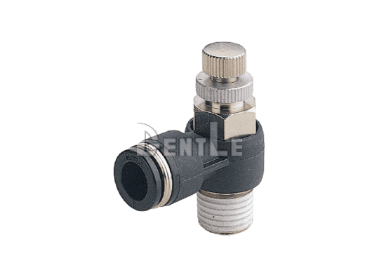
- Straight type (SC series): For linear installation near cylinders
- Elbow type (SS series): For narrow spaces requiring angled piping
4. Maximum Operating Pressure and Durability
Recommended features include:
- High-pressure-resistant brass body
- Vibration-resistant structure
- Fast-response check valve
These improve durability and cylinder control sensitivity.
5. Dust-Proof and Leak-Proof Design
High-quality designs may include:
- Dual O-ring sealing
- Precision needle valve
- Leak-resistant structure
- Ozone-resistant materials
These features directly affect service life and operational stability.
Conclusion
Although a speed controller is a small component, it has a significant impact on equipment performance.
Proper installation ensures smooth cylinder motion without vibration. Correct installation direction, gradual speed adjustment, and proper specification selection will result in safer, more durable, and more stable operation.
Standard Type Speed Controllers
Further Reading:
What Is a Speed Controller? Function, Installation, and Quick Setup Guide
What is a Pneumatic Flow Control Valve? Key Functions, Principles, and Applications Uncovered!